Appearance
Generally speaking, Voxel Worlds are the result of many combined stamps, and it can be hard to understand why the result looks the way it does. While there is tooling on the graph side to help debug the graphs assigned to individual stamps, there are many issues where you need to look beyond individual stamps. Voxel Plugin includes a handful of tools designed to help debug why the generated world ends up looking the way it does.
Stamp Relevance List
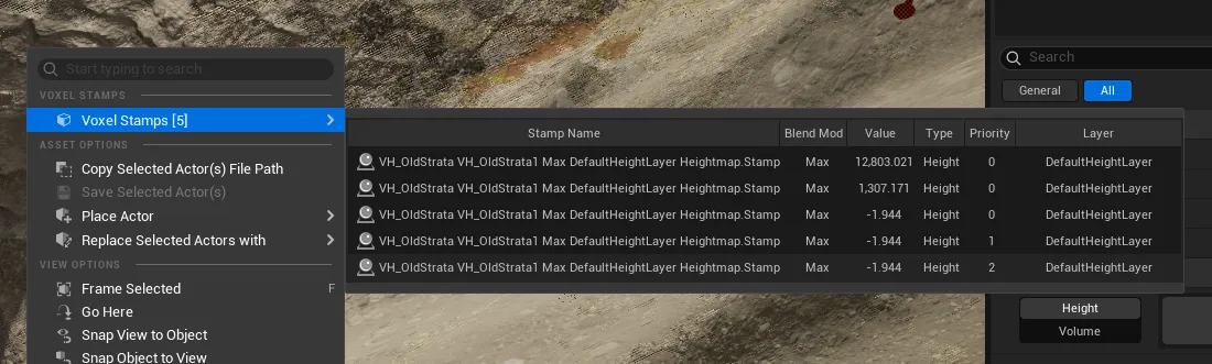
When right-clicking the Voxel World, the pop-up menu will include a Voxel Stamps option at the top. Hovering this will open a scrollable panel. This panel shows all stamps affecting the right-clicked position, showing their priority and output value (height or distance). Hovering over or clicking a stamp in this list will automatically select it in the viewport for further editing.
Voxel Debug Actor
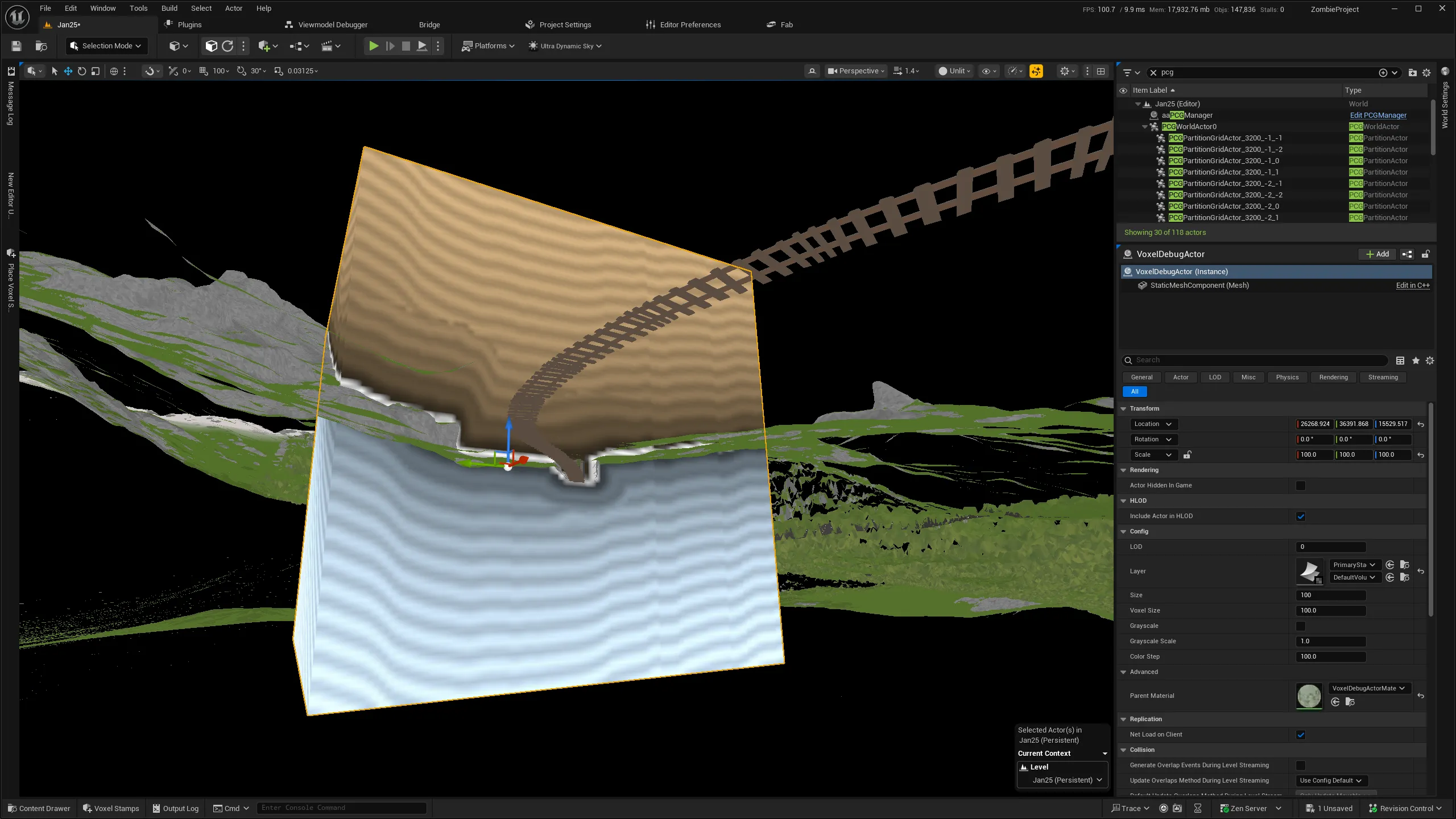
Voxel Debug Actors can be placed from the actor placement menu at the top of the editor. These actors query a layer from a stack (assigned from the details panel) and draw it as a surface material.
TIP
For best visibility, switch to the Unlit view mode when using Voxel Debug Actors.
Position your camera underneath the terrain (or hide the Voxel World entirely) to make it easier to see all sides of the distance field.
Areas shown in yellow represent air (positive distance), a white line represents the surface (where distance is 0), and blue means a location is inside the terrain (negative distance). The visualizer shows a 'line' pattern which represents the distance. When the distance field is consistent, lines will be mostly evenly spaced (like in the above image). Positions that have no valid distance (i.e. they are NaN/Void) will be shown as bright pink.
WARNING
Seeing voids in the debugger does not have to mean there an issue! Voids are expected/by design, and won't cause issues as long as there is a large enough band of valid distance around the surface.
If the line pattern is (very) irregular, the distance field is incorrect, which can lead to issues. For instance, Projection/Raymarching in PCG may not function well (or require very high step counts). In dramatic cases, inconsistent distance fields may lead to holes in the terrain.